Understanding Error Correction Mode
Initially found on more expensive fax machines, ECM is a feature that is found increasingly more often on today's fax devices. Defined by ITU-T Recommendation T.30 Annex A, ECM ensures a much higher level of fax page data integrity than what is consistently achieved on non-ECM G3 fax transactions. Whereas normal G3 fax transactions typically present a fax with acceptable quality, ECM usually guarantees near perfect quality.
The ECM feature is negotiated at the beginning of a fax call during the DIS/DCS message exchange. If both the sending and receiving fax devices support ECM, it is typically used during the fax call. If either device does not support or agree to ECM, the fax transaction will proceed as a normal G3, non-ECM call. This allows fax devices that support ECM to be compatible with other fax devices that do not support the feature.
During a non-ECM fax transaction, the error checking and error correction ability is limited, which allows for errors to corrupt the fax page data. The errors can come from a number of sources but are usually caused by impairments in the transmission path. If the number of errors is too great, an RTN message is usually sent by the receiving fax device. However, this RTN message does not guarantee that the corrupted page will be re-sent. Page errors during a non-ECM fax call are not usually corrected, as evidenced by received fax pages that suffer from poor quality.
When a non-ECM fax page suffers from poor quality and contains errors, you will see portions of the text on the page that are unreadable and distorted because bad scan lines cannot be resolved into meaningful information. The text on the page may also appear condensed or bunched up, or white horizontal streaks might be seen correlating with the bad scan lines.
ECM fax calls, on the other hand, have a method for accurately detecting and correcting errors in the fax page data. Each fax page is divided into one or more blocks of data. Within each of these blocks are HDLC frames that contain an FCS value to help ensure the integrity of the data. When the answering fax machine receives the block, it uses the FCS value to checksum each frame so that it can request a retransmission of any frames that contain errors. This retransmission process usually continues until all pages are correct or until the fax machines give up. Because of ECMs tenacity at getting pages sent correctly, faxes may take longer and sometimes not even complete. Most fax machines automatically redial if a fax transmission does not make it through. ECM relies on this automatic redial to try again at another time when there will be an opportunity for a better-quality connection.
Compared to a non-ECM fax call, ECM has the advantage of ensuring that page information is received error free. This is obviously important for transmissions such as legal documents containing small fonts. However, ECM faxes might take a long time or never complete in conditions where there are a lot of errors in the transmission path. You can see these kinds of conditions with poor-quality PSTN connections. If it is important to get the fax through quickly and having occasional page errors is acceptable, a non-ECM fax call might be advantageous. For these types of situations, most fax machines that support the ECM feature also include a means for disabling it.
ECM Call Analysis
Conceptually, an ECM fax call is almost identical to a non-ECM call. The important principle regarding ECM is that a fax page is broken into partial pages or blocks of a fixed size; it may take multiple partial pages or blocks to send a single fax page.
Figure 2-22 shows a two-page fax transaction using ECM. The first page is broken into two blocks while the second page fits into one block. Each block or partial page is followed by a partial page signal (PPS) message. A PPS-NULL message follows any partial page that is not the last block for a page. The last page block is followed by a PPS-MPS. For the final block of the last page, a PPS-EOP message signals that there are no further pages to be sent.
Figure 2-22 Two-Page Fax Transaction Using ECM
Figure 2-22 Two-Page Fax Transaction Using ECM
CNG (Calling Tone) 1100 Hz Every 3 Sec for .5 Sec
CED ( Called Terminal Identification) 2100 Hz Tone
DIS (Digital Identification Signal) with Optional NSF and CSI
DCS (Digital Command Signal) with Optional TSI
TCF (Training Check) High Speed Modulation Training
CFR (Confirmation to Receive)
Partial Page Transmission
PPS-NULL (Partial Page Sent)
MCF (Message Confirmation)
Partial Page Transmission
PPS-MPS (Partial Page Sent)
MCF (Message Confirmation)
Partial Page Transmission
PPS-EOP (Partial Page Sent)
PPR (Partial Page Request)
Partial Page Transmission
PPS-EOP (Partial Page Sent)
MCF (Message Confirmation)
DCN (Disconnect)
Call Setup/Tones
Low Speed
High Speed
The partial page transmissions shown in Figure 2-22 contain the actual fax page data, which is commonly referred to as fax coded data (FCD). The FCD is simply HDLC frames of a 64-or 256-byte size that also contain an FCF and a frame number. These HDLC frames are streamed at the negotiated high-speed modulation until the entire partial page or page block has been sent. At the end of the block, the low-speed, V.21-modulated PPS is found.
The partial page request (PPR) message is also occasionally seen in an ECM call flow. A PPR message details the specific portions of a partial page that contain errors. Upon receiving a PPR message, the transmitting device learns what errored portions of the partial page to resend. This prevents the retransmission of the entire block while ensuring that all the fax page data is received accurately. Figure 2-22 demonstrates how PPR works in an ECM call flow.
Notice in Figure 2-22 that the last page of the fax transaction is received with some errors. PPR is sent to the transmitter requesting a retransmission of the portion of the partial page that is corrupted. This corrupted portion of the block is then retransmitted using another partial page message. No errors are detected in the retransmission, and the partial page is confirmed, followed by a DCN.
PPS and PPR
Figure 2-23 illustrates an ECM PPS message. Unlike a typical T.30 message, the main distinguishing characteristic of the PPS message is the presence of a second FCF. You might have noticed in Figure 2-22 that PPS messages appear as PPS-MPS or PPS-EOP. The first FCF indicates the PPS message type, whereas the second FCF details an extension to the PPS message such as NULL, MPS, or EOP. Many of the values in the secondary FCF are identical to what is seen in a non-ECM fax call, and they also have the same meaning. For example, a PPS-MPS message and an MPS message are functionally equivalent, except that one follows a full page in a non-ECM call and the other follows a partial page when ECM is enabled. Both of these messages inform the receiving side that this page or partial page is complete and that additional page data will be sent pending a confirmation.
Like many other T.30 messages, there's no FIF as commonly seen in the DIS and DCS messages. However, instead of just an FCF by itself, the PPS message has three additional fields
• Page Counter(PC): Indicates the current page number
• Block Counter(BC): Indicates the block number within that page
• Frame Counter (FC): Specifies the total number of frames within the block
Figure 2-23 T.30 PPS Frame
Figure 2-23 T.30 PPS Frame

|
Flag |
Address |
Control |
Information |
FCS |
Flag |
|
01111110 |
11111111 |
11001000 |
01111110 |
|
FCF1 - PPS 11111101 |
FCF2 XXXXXXXX |
PC |
BC |
FC |
|
' 0000 0000 NULL |
Page |
Block |
Frame |
|
|
1 1111 0000 EOM |
Counter |
Counter |
Counter |
|
|
. 1111 0010 MPS |
||||
|
1 1111 0100 EOP |
||||
|
! 1111 1000 EOS |
||||
|
■ 1111 1001 PRI-EOM |
||||
|
J 1111 1010 PRI-MPS |
||||
|
! 1111 1100 PRI-EOP |
||||
The frames that the FC refers to are HDLC frames full of page data. Each HDLC frame is either 64 or 256 bytes depending on what is specified in the DCS message. Up to a maximum of 256 of these HDLC frames form a block with FC notating the exact number. If the page data requires more than 256 HDLC frames or 1 block, multiple blocks or partial pages are sent. By dividing the page data into blocks made up of HDLC frames, ECM takes advantage of HDLC's CRC function to verify small segments of page information. This provides more detailed error detection while preventing a full-page retransmission when error correction is necessary.
A PPR message occurs during an ECM fax transaction when there are errors in a partial page. The receiving device uses the PPR message to notify the transmitting device of the HDLC frames that have errors. The transmitting device then retransmits the HDLC frames specified by the PPR message. Figure 2-24 illustrates the PPR message format.
Figure 2-24 T.30 PPR Frame
Figure 2-24 T.30 PPR Frame
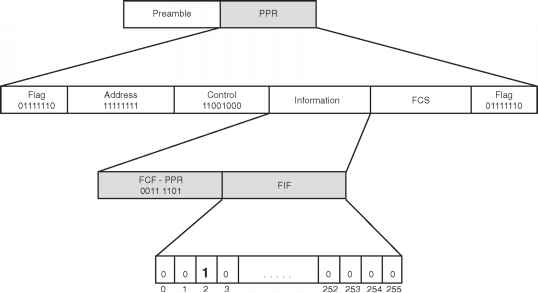
- Retransmission Requested for Frame 2
The PPR frame format contains the standard 1-byte FCF followed by a 256-bit FIF. The 256 bits in the FIF correspond to the 256 HDLC frames that were just received in the preceding partial page. Any frames that were received with errors are flagged by setting the corresponding PPR FIF bit to 1. HDLC frames that were received correctly have a bit setting of 0. Implementing this error correction methodology allows ECM to easily notify the sender of corrupted frames. These frames are then re-sent by the originating fax device before proceeding to the next partial page.
Post a comment