Layer 2 Protocol Tunneling
|
m |
|||||||||||||||||||||||||||||||||||||||||||||||||||||||||||||||||||||||||||||||||||||
|
Asymmetric Link Customer A Site 2 VLANs 1 to 100 Customer A Site 2 VLANs 1 to 100 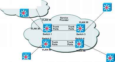
Trunk Asymmetric Link Customer B Site 1 © 2002, Cisco Systems, VLANSsI to 200 Customer B Site 2 VLANS 1 to 200 Cisco CCIE Prep v1.0—Module 5-30 Customer B Site 1 © 2002, Cisco Systems, VLANSsI to 200 Customer B Site 2 VLANS 1 to 200 Cisco CCIE Prep v1.0—Module 5-30 Customers that have different sites connected across a service-provider network and want to scale this topology into one large layer 2 domain need to run various Layer 2 protocols between sites. For example, STP must run properly, and every VLAN should build a proper spanning tree that includes the local site and all remote sites across the service-provider infrastructure. Cisco Discovery Protocol (CDP) must discover neighboring Cisco devices from local and remote sites. VLAN Trunking Protocol (VTP) must provide consistent VLAN configuration throughout all sites in the customer network. When protocol tunneling is enabled, edge switches on the inbound side of the service-provider infrastructure encapsulate Layer 2 protocol packets with a special MAC address and send them across the service-provider network. Core switches in the network do not process these packets, but forward them as normal packets. Layer 2 protocol data units (PDUs) for CDP, STP, or VTP cross the service-provider infrastructure and are delivered to customer switches on the outbound side of the service-provider network. Identical packets are received by all customer ports on the same VLANs with the following results: ■ Switches at each of a customer's sites are able to properly run STP and every VLAN can build a correct spanning tree based on parameters from all sites and not just from the local site. CDP discovers and shows information about the other Cisco devices connected through the service-provider network. VTP provides consistent VLAN configuration throughout the customer network, propagating through the service provider to all switches. Layer 2 protocol tunneling can be used independently or to enhance 802.1Q tunneling. If protocol tunneling is not enabled on 802.1Q tunneling ports, remote switches at the receiving end of the service-provider network do not receive the PDUs and cannot properly run STP, CDP, and VTP. When protocol tunneling is enabled, Layer 2 protocols within each customer's network are totally separate from those running within the service-provider network. Customer switches at different sites that send traffic through the service-provider network with 802.1Q tunneling achieve complete knowledge of the customer's VLAN. If 802.1Q tunneling is not used, you can still enable Layer 2 protocol tunneling by connecting to the customer switch through access ports and enabling tunneling on the service-provider access port. 3550(config)# interface faO/1 3550(config-if)# switchport mode access 3550(config-if)# 12protocol-tunnel vtp 3550(config-if)# exit 3550(config)# errdisable recovery cause 12ptguard 3550(config)# 12protoco1-tunne1 cos 5 3550(config)# interface faO/1 3550(config-if)# switchport mode access 3550(config-if)# 12protocol-tunnel vtp 3550(config-if)# exit 3550(config)# errdisable recovery cause 12ptguard 3550(config)# 12protoco1-tunne1 cos 5 -ESI VTP Domain: CCIE VTP Domain: CCIE © 2002, Cisco Systems, Inc. All rights reservec Cisco CCIE Prep v1.0—MoCule 5-31 You enable Layer 2 protocol tunneling (by protocol) on the access ports or tunnel ports that are connected to the customer in the edge switches of the service-provider network. Edge-switch tunnel ports are connected to customer 802.1Q trunk ports; edge-switch access ports are connected to customer access ports. The Catalyst 3550 switch supports Layer 2 protocol tunneling for CDP, STP, and VTP. The edge switches connected to the customer switch perform the tunneling process. When the Layer 2 PDUs that entered the inbound edge switch through the tunnel or access port exit the switch through the trunk port into the service-provider network, the switch overwrites the customer PDU-destination MAC address with a well-known Cisco proprietary multicast address (01-00-0c-cd-cd-d0). If 802.1Q tunneling is enabled, packets are also double-tagged; the outer tag is the customer metro tag and the inner tag is the customer VLAN tag. The core switches ignore the inner tags and forward the packet to all trunk ports in the same metro VLAN. The edge switches on the outbound side restore the proper Layer 2 protocol and MAC address information and forward the packets to all tunnel or access ports in the same metro VLAN. Therefore, the Layer 2 PDUs are kept intact and delivered across the service-provider infrastructure to the other side of the customer network. Use the steps outlined in the following table to configure a port for Layer 2 protocol tunneling:
These are some configuration guidelines and operating characteristics of Layer 2 protocol These are some configuration guidelines and operating characteristics of Layer 2 protocol tunneling: ■ The switch supports tunneling of CDP, STP, including multiple STP (MSTP), and VTP protocols. Protocol tunneling is disabled by default but can be enabled for the individual protocols on 802.1Q tunnel ports or on access ports. ■ Tunneling is not supported on trunk ports.If you enter the 12protocol-tunnel interface configuration command on a trunk port, the command is accepted, but Layer 2 tunneling does not take affect unless you change the port to a tunnel port or access port. ■ EtherChannel port groups are compatible with tunnel ports as long as the 802.1Q configuration is consistent within an EtherChannel port group. ■ If an encapsulated PDU (with the proprietary destination MAC address) is received from a tunnel port or access port with Layer 2 tunneling enabled, the tunnel port is shut down to prevent loops. The port also shuts down when a configured shutdown threshold for the protocol is reached. You can manually re-enable the port (by issuing a shutdown, no shutdown command sequence) or if errdisable recovery is enabled, the operation is retried after a specified time interval. ■ Only decapsulated PDUs are forwarded to the customer network. The spanning tree instance running on the service-provider network does not forward BPDUs to tunnel ports. No CDP packets are forwarded from tunnel ports. ■ When protocol tunneling is enabled on an interface, you can set a per protocol, per port, shutdown threshold for the PDUs generated by the customer network. If the limit is exceeded, the port is shut down. You can also rate-limit BPDUs by using QoS ACLs and policy maps on a tunnel port. ■ Because tunneled PDUs (especially STP BPDUs) must be delivered to all remote sites for the customer virtual network to operate properly, you can give PDUs higher priority within the service-provider network than data packets received from the same tunnel port. By default, the PDUs use the same CoS value as data packets. Verifying 802.1Q and Layer 2 Protocol Tunneling
© 2002, CiscoSystems, Inc. All rights reserved. Cisco CCIE Prep vl.O—Module 5-32 © 2002, CiscoSystems, Inc. All rights reserved. Cisco CCIE Prep vl.O—Module 5-32 The following table lists the commands used for verifying 802.1 Q and Layer 2 Protocol Tunneling:
The Catalyst 3550 supports two different types of Layer 3 interfaces: Router Ports, which are physical interfaces that act just like a physical interface on a Cisco IOS router, and Switched Virtual Interfaces (SVI), which are virtual VLAN interfaces used for InterVLAN routing, similar to the VLAN interfaces on the MSFC of the Catalyst 6500 series.
A routed port is a physical port that acts like a port on a router; it does not have to be connected to a router. A routed port is not associated with a particular VLAN, as is an access port. A routed port behaves like a regular router interface, except that it does not support VLAN subinterfaces. Routed ports can be configured with a Layer 3 routing protocol. Configure routed ports by putting the interface into Layer 3 mode with the no switchport interface configuration command. Then assign an IP address to the port, enable routing, and assign routing protocol characteristics by using the ip routing and router protocol global configuration commands. Note Entering a no switchport interface configuration command shuts the interface down and then re-enables it, which might generate messages on the device to which the interface is connected. Furthermore, when you use this command to put the interface into Layer 3 mode, you are deleting any Layer 2 characteristics configured on the interface. 
routing or bridging function in the system. Only one SVI can be associated with a VLAN, but you need to configure an SVI for a VLAN only when you wish to route between VLANs, fallback-bridge nonroutable protocols between VLANs, or to provide IP host connectivity to the switch. By default, an SVI is created for the default VLAN (VLAN 1) to permit remote switch administration. Additional SVIs must be explicitly configured. In Layer 2 mode, SVIs provide IP host connectivity only to the system; in Layer 3 mode, you can configure routing across SVIs. SVIs are created the first time that you enter the vlan interface configuration command for a VLAN interface. The VLAN corresponds to the VLAN tag associated with data frames on an ISL or 802.1Q encapsulated trunk or the VLAN ID configured for an access port. Configure a VLAN interface for each VLAN for which you want to route traffic, and assign it an IP address. Note When you create an SVI, it does not become active until it is associated with a physical port. Routed ports and SVIs support routing protocols (including Multicast routing) and bridging configurations. The process of configuring IP addresses and routing protocols on the Catalyst 3550 is the same as any IOS-based device (Cisco router). Many of the IOS commands learned in this course also apply to the Catalyst 3550. All Layer 3 interfaces require an IP address to route traffic. The number of routed ports and SVIs that you can configure is not limited by software; however, the interrelationship between this number and the number of other features being configured might have an impact on CPU utilization because of hardware limitations. The following commands are applicable to all interfaces; logical or physical, Layer 2 or Layer 3, on the Catalyst 3550. 3550> enable 35 5 0# config t 3550(config)# interface fastEthernet 0/3 3550(config-if)# speed 100 3550(config-if)# duplex full 3550> enable 35 5 0# config t 3550(config)# interface fastEthernet 0/3 3550(config-if)# speed 100 3550(config-if)# duplex full 
© 2002, Cisco Systems, Inc. All rights reservec Cisco CCIE Prep v1.0—MoCule 5-35 Ethernet interfaces on the Catalyst 3550 switch operate in 10, 100, or 1000 Mbps and in either full or half duplex mode. In full-duplex mode, two stations can send and receive at the same time. When packets can flow in both directions simultaneously, effective Ethernet bandwidth doubles to 20 Mbps for Ethernet interfaces, to 200 Mbps for Fast Ethernet interfaces, and to 2 Gbps for Gigabit interfaces. Full-duplex communication is often an effective solution to collisions, which are major constrictions in Ethernet networks. Normally, Ethernet ports operate in half-duplex mode, which means that stations can either receive or send. You can configure interface speed on Fast Ethernet (10/100-Mbps) and Gigabit Ethernet (10/100/1000-Mbps) interfaces; you cannot configure speed on Gigabit Interface Converter (GBIC) interfaces. You can configure duplex mode on any Fast Ethernet or Gigabit Ethernet interfaces that are not set to autonegotiate; you cannot configure duplex mode on GBIC interfaces. Use the steps outlined in the following table to set the speed and duplex mode for a 10/100/1000 Ethernet interface: Recommended ProgramsReaders' Questions
Note Use the no speed and no duplex interface configuration commands to return the interface to the default speed and duplex settings (autonegotiate). To return all interface settings to the defaults, use the default interface interface-id interface configuration command. Continue reading here: Verifying Interface Status Was this article helpful? |
|||||||||||||||||||||||||||||||||||||||||||||||||||||||||||||||||||||||||||||||||||||

